
5.8 : Dipôles électriques
- Page ID
- 191081

À la fin de cette section, vous serez en mesure de :
- Décrire un dipôle permanent
- Décrire un dipôle induit
- Définir et calculer un moment dipolaire électrique
- Expliquer la signification physique du moment dipolaire
Plus tôt, nous avons discuté et calculé le champ électrique d'un dipôle : deux charges égales et opposées qui sont « proches » l'une de l'autre. (Dans ce contexte, « proche » signifie que la distance d entre les deux charges est très, bien inférieure à la distance du point de champ P, l'endroit où vous calculez le champ.) Voyons maintenant ce qui arrive à un dipôle lorsqu'il est placé dans un champ externe\(\vec{E}\). Nous supposons que le dipôle est un dipôle permanent ; il existe sans le champ et ne se décompose pas dans le champ externe.
Rotation d'un dipôle due à un champ électrique
Pour l'instant, nous ne traitons que du cas le plus simple : le champ extérieur est uniforme dans l'espace. Supposons que nous ayons la situation décrite sur la figure\(\PageIndex{1}\), où nous désignons la distance entre les charges comme vecteur\(\vec{d}\), pointant de la charge négative à la charge positive.
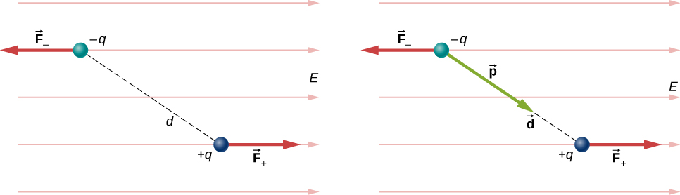
The forces on the two charges are equal and opposite, so there is no net force on the dipole. However, there is a torque:
\[\begin{align} \vec{r} &= \left(\dfrac{\vec{d}}{2} \times \vec{F}_+ \right) + \left(- \dfrac{\vec{d}}{2} \times \vec{F}_- \right) \\[4pt] &= \left[ \left(\dfrac{\vec{d}}{2}\right) \times \left(+q\vec{E}\right) + \left(-\dfrac{\vec{d}}{2}\right) \times \left(-q\vec{E}\right)\right] \\[4pt] &= q\vec{d} \times \vec{E}. \end{align}\]
The quantity \(qd\) (the magnitude of each charge multiplied by the vector distance between them) is a property of the dipole; its value, as you can see, determines the torque that the dipole experiences in the external field. It is useful, therefore, to define this product as the so-called dipole moment of the dipole:
\[\vec{p} \equiv q\vec{d}.\]
We can therefore write
\[\vec{r} = \vec{p} \times \vec{E}.\]
Recall that a torque changes the angular velocity of an object, the dipole, in this case. In this situation, the effect is to rotate the dipole (that is, align the direction of \(\vec{p}\)) so that it is parallel to the direction of the external field.
Induced Dipoles
Neutral atoms are, by definition, electrically neutral; they have equal amounts of positive and negative charge. Furthermore, since they are spherically symmetrical, they do not have a “built-in” dipole moment the way most asymmetrical molecules do. They obtain one, however, when placed in an external electric field, because the external field causes oppositely directed forces on the positive nucleus of the atom versus the negative electrons that surround the nucleus. The result is a new charge distribution of the atom, and therefore, an induced dipole moment (Figure \(\PageIndex{2}\)).
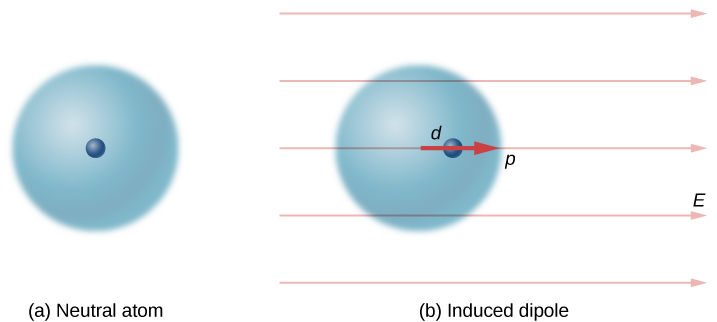
An important fact here is that, just as for a rotated polar molecule, the result is that the dipole moment ends up aligned parallel to the external electric field. Generally, the magnitude of an induced dipole is much smaller than that of an inherent dipole. For both kinds of dipoles, notice that once the alignment of the dipole (rotated or induced) is complete, the net effect is to decrease the total electric field
\[\vec{E}_{total} = \vec{E}_{external} + \vec{E}_{dipole}\]
in the regions outside the dipole charges (Figure \(\PageIndex{3}\)). By “outside” we mean further from the charges than they are from each other. This effect is crucial for capacitors, as you will see in Capacitance.
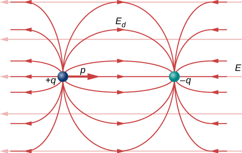
Recall that we found the electric field of a dipole. If we rewrite it in terms of the dipole moment we get:
\[\vec{E}(z) = \dfrac{1}{4 \pi \epsilon_0} \dfrac{\vec{p}}{z^3}.\]
The form of this field is shown in Figure \(\PageIndex{3}\). Notice that along the plane perpendicular to the axis of the dipole and midway between the charges, the direction of the electric field is opposite that of the dipole and gets weaker the further from the axis one goes. Similarly, on the axis of the dipole (but outside it), the field points in the same direction as the dipole, again getting weaker the further one gets from the charges.