
9.5: Sheria ya Ohm
- Page ID
- 176233

Mwishoni mwa sehemu hii, utaweza:
- Eleza sheria ya Ohm
- Kutambua wakati sheria ya Ohm inatumika na wakati haina
Tumekuwa tukijadili mali tatu za umeme hadi sasa katika sura hii: sasa, voltage, na upinzani. Inageuka kuwa vifaa vingi vinaonyesha uhusiano rahisi kati ya maadili ya mali hizi, inayojulikana kama sheria ya Ohm. Vifaa vingine vingi havionyeshi uhusiano huu, hivyo licha ya kuitwa sheria ya Ohm, haionekani kuwa sheria ya asili, kama sheria za Newton au sheria za thermodynamics. Lakini ni muhimu sana kwa mahesabu yanayohusisha vifaa vinavyotii sheria ya Ohm.
Maelezo ya Sheria ya Ohm
Ya sasa ambayo inapita kwa njia ya vitu vingi ni sawa sawa na voltage V inayotumiwa nayo. Mwanafizikia wa Ujerumani Georg Simon Ohm (1787—1854) alikuwa wa kwanza kuonyesha majaribio kwamba sasa katika waya ya chuma ni sawia moja kwa moja na voltage inayotumika:
\[I \propto V.\]
Uhusiano huu muhimu ni msingi wa sheria ya Ohm. Inaweza kutazamwa kama uhusiano wa sababu-na-athari, na voltage sababu na sasa athari. Hii ni sheria ya upimaji, ambayo ni kusema kwamba ni jambo la majaribio lililozingatiwa, kama msuguano. Uhusiano huo wa mstari haufanyiki kila wakati. Nyenzo yoyote, sehemu, au kifaa kinachotii sheria ya Ohm, ambapo sasa kupitia kifaa ni sawia na voltage inayotumiwa, inajulikana kama nyenzo za ohmic au sehemu ya ohmic. Nyenzo yoyote au sehemu ambayo haitii sheria ya Ohm inajulikana kama nyenzo zisizo na nonohmic au sehemu ya nonohmic.
Majaribio ya Ohm
Katika karatasi iliyochapishwa mwaka wa 1827, Georg Ohm alielezea jaribio ambalo alipima voltage kote na sasa kupitia nyaya mbalimbali za umeme zilizo na urefu mbalimbali wa waya. Jaribio sawa linaonyeshwa kwenye Kielelezo\(\PageIndex{1}\). Jaribio hili linatumiwa kuchunguza sasa kwa njia ya kupinga ambayo inatokana na voltage iliyotumiwa. Katika mzunguko huu rahisi, kupinga ni kushikamana katika mfululizo na betri. Voltage inapimwa na voltmeter, ambayo inapaswa kuwekwa kwenye kupinga (sambamba na kupinga). Ya sasa inapimwa na ammeter, ambayo inapaswa kuwa sawa na kupinga (katika mfululizo na kupinga).
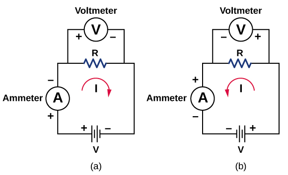
In this updated version of Ohm’s original experiment, several measurements of the current were made for several different voltages. When the battery was hooked up as in Figure \(\PageIndex{1a}\), the current flowed in the clockwise direction and the readings of the voltmeter and ammeter were positive. Does the behavior of the current change if the current flowed in the opposite direction? To get the current to flow in the opposite direction, the leads of the battery can be switched. When the leads of the battery were switched, the readings of the voltmeter and ammeter readings were negative because the current flowed in the opposite direction, in this case, counterclockwise. Results of a similar experiment are shown in Figure \(\PageIndex{2}\).

In this experiment, the voltage applied across the resistor varies from −10.00 to +10.00 V, by increments of 1.00 V. The current through the resistor and the voltage across the resistor are measured. A plot is made of the voltage versus the current, and the result is approximately linear. The slope of the line is the resistance, or the voltage divided by the current. This result is known as Ohm’s law:
\[V = IR \label{Ohms}\]
where V is the voltage measured in volts across the object in question, I is the current measured through the object in amps, and R is the resistance in units of ohms. As stated previously, any device that shows a linear relationship between the voltage and the current is known as an ohmic device. A resistor is therefore an ohmic device.
A carbon resistor at room temperature \((20^oC)\) is attached to a 9.00-V battery and the current measured through the resistor is 3.00 mA. (a) What is the resistance of the resistor measured in ohms? (b) If the temperature of the resistor is increased to \(60^oC\) by heating the resistor, what is the current through the resistor?
Strategy
(a) The resistance can be found using Ohm’s law. Ohm’s law states that \(V = IR\), so the resistance can be found using \(R = V/I\).
(b) First, the resistance is temperature dependent so the new resistance after the resistor has been heated can be found using \(R = R_0 (1 + \alpha \Delta T)\). The current can be found using Ohm’s law in the form \(I = V/R\).
Solution
- Using Ohm’s law and solving for the resistance yields the resistance at room temperature: \[R = \dfrac{V}{I} = \dfrac{9.00 \, V}{3.00 \times 10^{-3} A} = 3.00 \times 10^3 \, \Omega = 3.00 k\Omega\]
- The resistance at \(60^oC\) can be found using \(R = R_0 (1 + \alpha \Delta T)\) where the temperature coefficient for carbon is \(\alpha = -0.0005\). \[R = R_0 (1 + \alpha \Delta T) = 3.00 \times 10^3 (1 - 0.0005 (60^oC - 20^oC)) = 2.94 \, k\Omega.\] The current through the heated resistor is \[I = \dfrac{V}{R} = \dfrac{9.00 \, V}{2.94 \times 10^3 \, \Omega} = 3.06 \times 10^{-3} A = 3.06 \, mA.\]
Significance
A change in temperature of \(40^oC\) resulted in a 2.00% change in current. This may not seem like a very great change, but changing electrical characteristics can have a strong effect on the circuits. For this reason, many electronic appliances, such as computers, contain fans to remove the heat dissipated by components in the electric circuits.
The voltage supplied to your house varies as \(V(t) = V_{max} sin \, (2\pi \, ft)\). If a resistor is connected across this voltage, will Ohm’s law \(V = IR\) still be valid?
- Answer
-
Yes, Ohm’s law is still valid. At every point in time the current is equal to \(I(t) = V(t) /R\), so the current is also a function of time, \(I(t) = \dfrac{V_{max}}{R} \, sin \, (2\pi \, ft)\).
See how Ohm’s law (Equation \ref{Ohms}) relates to a simple circuit. Adjust the voltage and resistance, and see the current change according to Ohm’s law. The sizes of the symbols in the equation change to match the circuit diagram.
Nonohmic devices do not exhibit a linear relationship between the voltage and the current. One such device is the semiconducting circuit element known as a diode. A diode is a circuit device that allows current flow in only one direction. A diagram of a simple circuit consisting of a battery, a diode, and a resistor is shown in Figure \(\PageIndex{3}\). Although we do not cover the theory of the diode in this section, the diode can be tested to see if it is an ohmic or a nonohmic device.

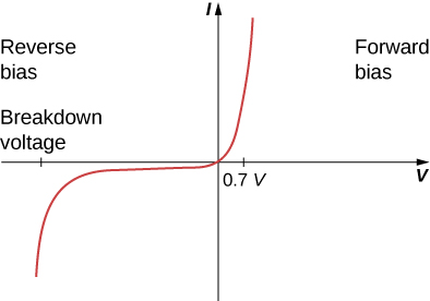
A plot of current versus voltage is shown in Figure \(\PageIndex{4}\). Note that the behavior of the diode is shown as current versus voltage, whereas the resistor operation was shown as voltage versus current. A diode consists of an anode and a cathode. When the anode is at a negative potential and the cathode is at a positive potential, as shown in part (a), the diode is said to have reverse bias. With reverse bias, the diode has an extremely large resistance and there is very little current flow—essentially zero current—through the diode and the resistor. As the voltage applied to the circuit increases, the current remains essentially zero, until the voltage reaches the breakdown voltage and the diode conducts current. When the battery and the potential across the diode are reversed, making the anode positive and the cathode negative, the diode conducts and current flows through the diode if the voltage is greater than 0.7 V. The resistance of the diode is close to zero. (This is the reason for the resistor in the circuit; if it were not there, the current would become very large.) You can see from the graph in Figure \(\PageIndex{4}\) that the voltage and the current do not have a linear relationship. Thus, the diode is an example of a nonohmic device.
Ohm’s law is commonly stated as \(V = IR\), but originally it was stated as a microscopic view, in terms of the current density, the conductivity, and the electrical field. This microscopic view suggests the proportionality \(V \propto I\) comes from the drift velocity of the free electrons in the metal that results from an applied electrical field. As stated earlier, the current density is proportional to the applied electrical field. The reformulation of Ohm’s law is credited to Gustav Kirchhoff, whose name we will see again in the next chapter.