8.6: Mfano wa Masi ya Dielectric
- Page ID
- 176374
Mwishoni mwa sehemu hii, utaweza:
- Eleza polarization ya dielectric katika uwanja sare umeme
- Eleza athari za dielectric polarized kwenye uwanja wa umeme kati ya sahani za capacitor
- Eleza uharibifu wa dielectric
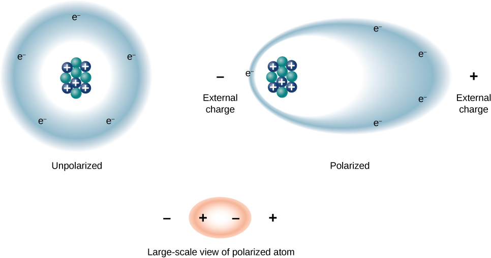
Tunaweza kuelewa athari za dielectric juu ya uwezo kwa kuangalia tabia yake katika ngazi ya Masi. Kama tulivyoona katika sura za awali, kwa ujumla, molekuli zote zinaweza kuhesabiwa kama polar au zisizo na polar. Kuna mgawanyo wa wavu wa mashtaka mazuri na hasi katika molekuli ya pekee ya polar, ambapo hakuna mgawanyo wa malipo katika molekuli isiyo ya kawaida ya pekee (Kielelezo\(\PageIndex{1}\)). Kwa maneno mengine, molekuli za polar zina muda wa kudumu wa umeme-dipole na molekuli zisizo za polar hazipaswi. Kwa mfano, molekuli ya maji ni polar, na molekuli ya oksijeni ni nonpolar. Molekuli zisizo na polar zinaweza kuwa polar mbele ya uwanja wa nje wa umeme, unaoitwa ikiwa polarization.

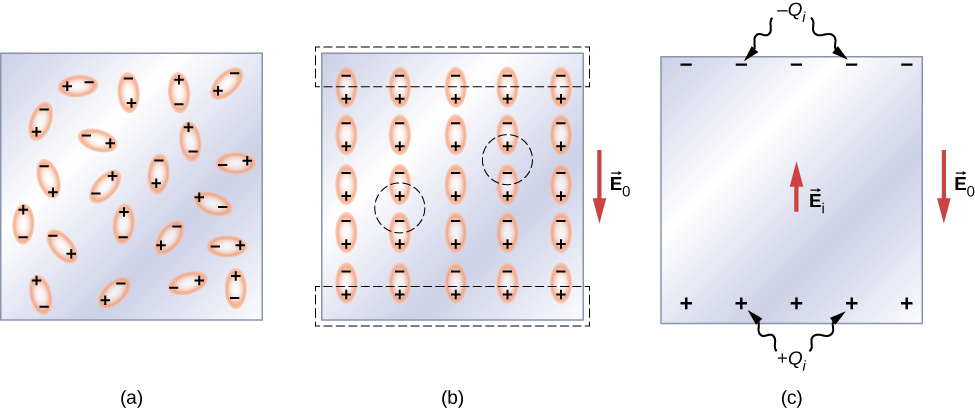
Hebu kwanza tuchunguze dielectric linajumuisha molekuli za polar. Kutokuwepo kwa shamba lolote la nje la umeme, dipoles za umeme zinaelekezwa nasibu, kama ilivyoonyeshwa kwenye Mchoro\(\PageIndex{2a}\). Hata hivyo, ikiwa dielectric imewekwa kwenye uwanja wa nje wa umeme\(\vec{E}_0\), molekuli za polar zinafanana na shamba la nje, kama inavyoonekana katika\(\PageIndex{2b}\) takwimu. Mashtaka kinyume na dipoles karibu ndani ya kiasi cha dielectric neutralize kila mmoja, kwa hiyo hakuna malipo ya wavu ndani ya dielectric (tazama duru zilizopigwa kwa sehemu (b)). Hata hivyo, hii sio karibu sana na nyuso za juu na za chini zinazopakana na dielectric (kanda iliyoambatanishwa na rectangles iliyopigwa ndani\(\PageIndex{2b}\), ambapo alignment haina kuzalisha malipo wavu. Kwa kuwa uwanja wa nje wa umeme unalinganisha tu dipoles, dielectric kwa ujumla ni neutral, na mashtaka ya uso ikiwa kwenye nyuso zake kinyume ni sawa na kinyume. Hizi ikiwa mashtaka ya uso\(+Q_i\) na\(-Q_i\) kuzalisha shamba la ziada la umeme\(\vec{E}_i\) (uwanja wa umeme unaojitokeza), ambalo linapinga shamba la nje\(\vec{E}_0\), kama ilivyoonyeshwa katika sehemu (c).

Athari sawa huzalishwa wakati molekuli ya dielectric ni nonpolar. Katika kesi hiyo, molekuli isiyo ya kawaida hupata wakati wa umeme wa dipole kwa sababu shamba la nje\(\vec{E}_0\) husababisha kujitenga kati ya mashtaka yake mazuri na mabaya. Dipoles ikiwa ya molekuli zisizo za polar zinafanana na\(\vec{E}_0\) njia sawa na dipoles ya kudumu ya molekuli za polar zimeunganishwa (inavyoonekana katika sehemu (b)). Kwa hiyo, uwanja wa umeme ndani ya dielectric umepungua bila kujali kama molekuli zake ni polar au zisizo na polar.
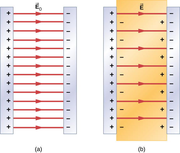
Kwa hiyo, wakati kanda kati ya sahani sambamba za capacitor kushtakiwa, kama vile ilivyoonyeshwa kwenye Kielelezo\(\PageIndex{3a}\), imejaa dielectric, ndani ya dielectric kuna uwanja wa umeme\(\vec{E}_0\) kutokana na malipo ya bure \(Q_0\)kwenye sahani za capacitor na uwanja wa umeme\(\vec{E}_i\) kutokana na malipo\(Q_i\) yaliyotokana na nyuso za dielectric. Jumla yao ya vector inatoa uwanja wa umeme wa wavu\(\vec{E}\) ndani ya dielectric kati ya sahani za capacitor (iliyoonyeshwa katika sehemu (b) ya takwimu):
\[\vec{E} = \vec{E}_0 + \vec{E}_i. \label{eq1}\]
Shamba hili la wavu linaweza kuchukuliwa kuwa shamba lililozalishwa na malipo ya ufanisi\(Q_0 - Q_i\) kwenye capacitor.

In most dielectrics, the net electrical field \(\vec{E}\) is proportional to the field \(\vec{E}_0\) produced by the free charge. In terms of these two electrical fields, the dielectric constant \(\kappa\) of the material is defined as
\[\kappa = \dfrac{E_0}{E}. \label{eq2}\]
Since \(\vec{E}_0\) and \(\vec{E}_i\) point in opposite directions, the magnitude E is smaller than the magnitude \(\vec{E}_0\) and therefore \(\kappa > 1\). Combining Equations \ref{eq1} with \ref{eq2}, and rearranging the terms, yields the following expression for the induced electrical field in a dielectric:
\[\vec{E}_i = \left(\dfrac{1}{\kappa} - 1 \right) \vec{E}_0. \label{eq3}\]
When the magnitude of an external electrical field becomes too large, the molecules of dielectric material start to become ionized. A molecule or an atom is ionized when one or more electrons are removed from it and become free electrons, no longer bound to the molecular or atomic structure. When this happens, the material can conduct, thereby allowing charge to move through the dielectric from one capacitor plate to the other. This phenomenon is called dielectric breakdown. (Figure 8.1.1 shows typical random-path patterns of electrical discharge during dielectric breakdown.) The critical value, \(E_c\) of the electrical field at which the molecules of an insulator become ionized is called the dielectric strength of the material. The dielectric strength imposes a limit on the voltage that can be applied for a given plate separation in a capacitor. For example, the dielectric strength of air is \(E_c = 3.0 \, MV/m\), so for an air-filled capacitor with a plate separation of \(d = 1.00 \, mm\), the limit on the potential difference that can be safely applied across its plates without causing dielectric breakdown is \(V = E_c d = (3.0 \times 10^6 V/m)(1.00 \times 10^{-3} m) = 3.0 \, kV\).
However, this limit becomes 60.0 kV when the same capacitor is filled with Teflon™, whose dielectric strength is about \(60.0 \, MV/m\). Because of this limit imposed by the dielectric strength, the amount of charge that an air-filled capacitor can store is only \(Q_0 = \kappa_{air} C_0(3.0 \, kV)\) and the charge stored on the same Teflon™-filled capacitor can be as much as
\[\begin{align} Q &= \kappa_{teflon}C_0 (60.0 \, kV) \nonumber \\[4pt] &= \kappa_{teflon} \dfrac{Q_0}{\kappa_{air}(3.0 \, kV)} (60.0 \, kV) \nonumber \\[4pt] &= 20 \dfrac{\kappa_{teflon}}{\kappa_{air}}Q_0 = 20\dfrac{2.1}{1.00059}Q_0 \nonumber \\[4pt] &\cong 42 Q_0. \end{align} \]
which is about 42 times greater than a charge stored on an air-filled capacitor. Typical values of dielectric constants and dielectric strengths for various materials are given in Table \(\PageIndex{1}\). Notice that the dielectric constant \(\kappa\) is exactly 1.0 for a vacuum (the empty space serves as a reference condition) and very close to 1.0 for air under normal conditions (normal pressure at room temperature). These two values are so close that, in fact, the properties of an air-filled capacitor are essentially the same as those of an empty capacitor.
| Material | Dielectric constant \(\kappa\) | Dielectric strength \(E_c [\times 10^6 \, V/m]\) |
|---|---|---|
| Vacuum | \(\kappa\)">1 | \(E_c [\times 10^6 \, V/m]\)">\(\infty\) |
| Dry air (1 atm) | \(\kappa\)">1.00059 | \(E_c [\times 10^6 \, V/m]\)">3.0 |
| Teflon™ | \(\kappa\)">2.1 | \(E_c [\times 10^6 \, V/m]\)">60 to 173 |
| Paraffin | \(\kappa\)">2.3 | \(E_c [\times 10^6 \, V/m]\)">11 |
| Silicon oil | \(\kappa\)">2.5 | \(E_c [\times 10^6 \, V/m]\)">10 to 15 |
| Polystyrene | \(\kappa\)">2.56 | \(E_c [\times 10^6 \, V/m]\)">19.7 |
| Nylon | \(\kappa\)">3.4 | \(E_c [\times 10^6 \, V/m]\)">14 |
| Paper | \(\kappa\)">3.7 | \(E_c [\times 10^6 \, V/m]\)">16 |
| Fused quartz | \(\kappa\)">3.78 | \(E_c [\times 10^6 \, V/m]\)">8 |
| Glass | \(\kappa\)">4 to 6 | \(E_c [\times 10^6 \, V/m]\)">9.8 to 13.8 |
| Concrete | \(\kappa\)">4.5 | \(E_c [\times 10^6 \, V/m]\)">– |
| Bakelite | \(\kappa\)">4.9 | \(E_c [\times 10^6 \, V/m]\)">24 |
| Diamond | \(\kappa\)">5.5 | \(E_c [\times 10^6 \, V/m]\)">2,000 |
| Pyrex glass | \(\kappa\)">5.6 | \(E_c [\times 10^6 \, V/m]\)">14 |
| Mica | \(\kappa\)">6.0 | \(E_c [\times 10^6 \, V/m]\)">118 |
| Neoprene rubber | \(\kappa\)">6.7 | \(E_c [\times 10^6 \, V/m]\)">15.7 to 26.7 |
| Water | \(\kappa\)">80 | \(E_c [\times 10^6 \, V/m]\)">-− |
| Sulfuric acid | \(\kappa\)">84 to 100 | \(E_c [\times 10^6 \, V/m]\)">-− |
| Titanium dioxide | \(\kappa\)">86 to 173 | \(E_c [\times 10^6 \, V/m]\)">– |
| Strontium titanate | \(\kappa\)">310 | \(E_c [\times 10^6 \, V/m]\)">8 |
| Barium titanate | \(\kappa\)">1,200 to 10,000 | \(E_c [\times 10^6 \, V/m]\)">– |
| Calcium copper titanate | \(\kappa\)">> 250,000 | \(E_c [\times 10^6 \, V/m]\)">– |
Not all substances listed in the table are good insulators, despite their high dielectric constants. Water, for example, consists of polar molecules and has a large dielectric constant of about 80. In a water molecule, electrons are more likely found around the oxygen nucleus than around the hydrogen nuclei. This makes the oxygen end of the molecule slightly negative and leaves the hydrogens end slightly positive, which makes the molecule easy to align along an external electrical field, and thus water has a large dielectric constant. However, the polar nature of water molecules also makes water a good solvent for many substances, which produces undesirable effects, because any concentration of free ions in water conducts electricity.
Suppose that the distance between the plates of the capacitor in Example 8.5.1 is 2.0 mm and the area of each plate is \(4.5 \times 10^{-3} m^2\). Determine:
- the electrical field between the plates before and after the Teflon™ is inserted, and
- the surface charge induced on the Teflon™ surfaces.
Strategy
In part (a), we know that the voltage across the empty capacitor is \(V_0 = 40 \, V\), so to find the electrical fields we use the relation \(V = Ed\) and Equation \ref{eq3}. In part (b), knowing the magnitude of the electrical field, we use the expression for the magnitude of electrical field near a charged plate \(E = \sigma/\epsilon_0\), where \(\sigma\) is a uniform surface charge density caused by the surface charge. We use the value of free charge \(Q_0 = 8.0 \times 10^{-10} C\) obtained in Example 8.5.1.
Solution
- The electrical field \(E_0\) between the plates of an empty capacitor is \[E_0 = \dfrac{V_0}{d} = \dfrac{40 \, V}{2.0 \times 10^{-3} m} = 2.0 10^4 V/m. \nonumber\] The electrical field \(E\) with the Teflon™ in place is \[E = \dfrac{1}{\kappa}E_0 = \dfrac{1}{2.1}2.0 \times 10^4 V/m = 9.5 \times 10^3 \, V/m. \nonumber\]
- The effective charge on the capacitor is the difference between the free charge \(Q_0\) and the induced charge \(Q_i\). The electrical field in the Teflon™ is caused by this effective charge. Thus \[\begin{align*} E &= \dfrac{1}{\epsilon_0}\sigma \\[4pt] &= \dfrac{1}{\epsilon_0} \dfrac{Q_0 - Q_i}{A}.\end{align*}\] We invert this equation to obtain \(Q_i\), which yields \[\begin{align*} Q_i &= Q_0 - \epsilon_0AE \\[4pt] &= 8.0 \times 10^{-10}C - \left(8.85 \times 10^{-12} \dfrac{C^2}{N \cdot m^2}\right)(4.5 \times 10^{-3}m^2)\left(9.5 \times 10^3 \, \dfrac{V}{m}\right) \\[4pt] &= 4.2 \times 10^{-10}C = 0.42 \, nC. \end{align*} \nonumber\]
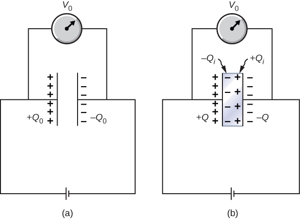
When a battery of voltage \(V_0\) is connected across an empty capacitor of capacitance \(C_0\), the charge on its plates is \(Q_0\), and the electrical field between its plates is \(E_0\). A dielectric of dielectric constant \(\kappa\) is inserted between the plates while the battery remains in place, as shown in Figure \(\PageIndex{4}\).
- Find the capacitance \(C\), the voltage \(V\) across the capacitor, and the electrical field \(E\) between the plates after the dielectric is inserted.
- Obtain an expression for the free charge \(Q\) on the plates of the filled capacitor and the induced charge \(Q_i\) on the dielectric surface in terms of the original plate charge \(Q_0\).

Strategy
We identify the known values:\(V_0, \, C_0, \, E_o, \, \kappa\), and \(Q_0\). Our task is to express the unknown values in terms of these known values.
Solution
(a) The capacitance of the filled capacitor is \(C = \kappa C_0\). Since the battery is always connected to the capacitor plates, the potential difference between them does not change; hence, \(V = V_0\). Because of that, the electrical field in the filled capacitor is the same as the field in the empty capacitor, so we can obtain directly that
\[E = \dfrac{V}{d} = \dfrac{V_0}{d} = E_0.\]
(b) For the filled capacitor, the free charge on the plates is
\[ \begin{align} Q &= CV \nonumber \\[4pt] &= (\kappa C_0)V_0 \nonumber \\[4pt] &= \kappa (C_0V_0) \nonumber \\[4pt] &= \kappa Q_0. \nonumber \end{align} \nonumber\]
The electrical field \(E\) in the filled capacitor is due to the effective charge \(Q - Q_i\) (Figure \(\PageIndex{4b}\)). Since \(E = E_0\), we have
\[\dfrac{Q - Q_i}{\epsilon_0 A} = \dfrac{Q_0}{\epsilon_0A}.\]
Solving this equation for \(Q_i\), we obtain for the induced charge
\[ \begin{align} Q_i &= Q - Q_0 \nonumber \\[4pt] &= \kappa Q_0 - Q_0 \nonumber \\[4pt] &= (\kappa -1)Q_0. \nonumber \end{align} \nonumber\]
Significance
Notice that for materials with dielectric constants larger than 2 (see Table \(\PageIndex{1}\)), the induced charge on the surface of dielectric is larger than the charge on the plates of a vacuum capacitor. The opposite is true for gasses like air whose dielectric constant is smaller than 2.
Continuing with Example \(\PageIndex{2}\), show that when the battery is connected across the plates the energy stored in dielectric-filled capacitor is \(U = \kappa U_0\) (larger than the energy \(U_0\) of an empty capacitor kept at the same voltage). Compare this result with the result \(U = U_0 /\kappa\) found previously for an isolated, charged capacitor.
Repeat the calculations of previous example for the case in which the battery remains connected while the dielectric is placed in the capacitor.
- Answer
-
a. \(C_0 = 20 \, pF\), \(C = 42 \, pF\);
b. \(Q_0 = 0.8 \, nC\), \(Q = 1.7 \, nC\):
c. \(V_0 = V = 40 \, V\);
d. \(U_0 = 16 \, nJ\), \(U = 34 \, nJ\)


