
8.6: Modelo molecular de um dielétrico
- Page ID
- 184635

Ao final desta seção, você poderá:
- Explicar a polarização de um dielétrico em um campo elétrico uniforme
- Descreva o efeito de um dielétrico polarizado no campo elétrico entre as placas do capacitor
- Explique a avaria dielétrica
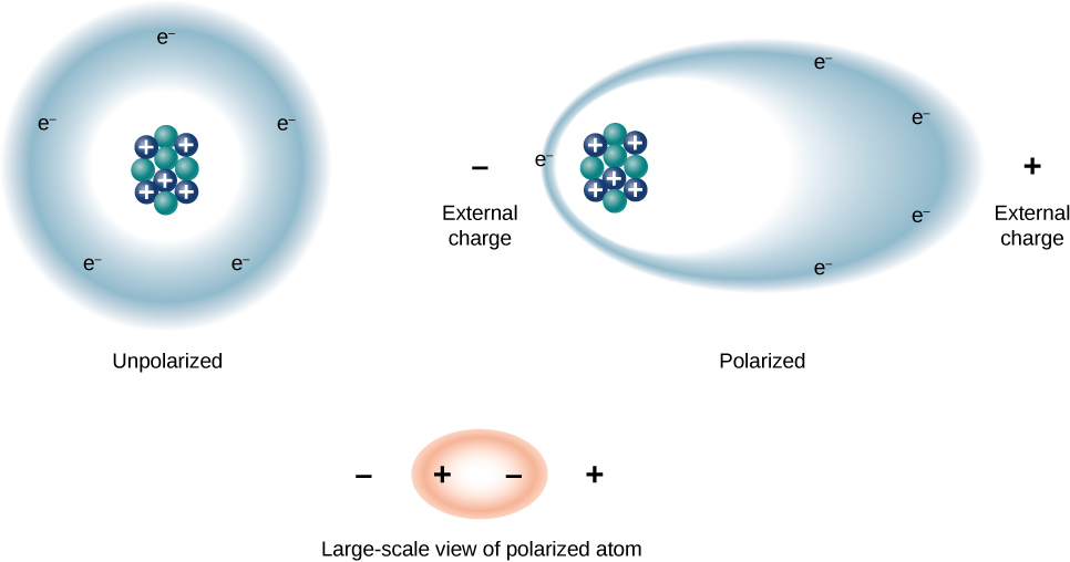
Podemos entender o efeito de um dielétrico na capacitância observando seu comportamento no nível molecular. Como vimos nos capítulos anteriores, em geral, todas as moléculas podem ser classificadas como polares ou não polares. Há uma separação líquida de cargas positivas e negativas em uma molécula polar isolada, enquanto não há separação de carga em uma molécula não polar isolada (Figura\(\PageIndex{1}\)). Em outras palavras, as moléculas polares têm momentos permanentes de dipolo elétrico e as moléculas não polares. Por exemplo, uma molécula de água é polar e uma molécula de oxigênio é apolar. As moléculas não polares podem se tornar polares na presença de um campo elétrico externo, o que é chamado de polarização induzida.
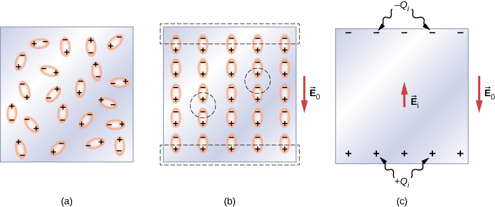
Vamos primeiro considerar um dielétrico composto por moléculas polares. Na ausência de qualquer campo elétrico externo, os dipolos elétricos são orientados aleatoriamente, conforme ilustrado na Figura\(\PageIndex{2a}\). No entanto, se o dielétrico for colocado em um campo elétrico externo\(\vec{E}_0\), as moléculas polares se alinham com o campo externo, conforme mostrado na\(\PageIndex{2b}\) figura. Cargas opostas em dipolos adjacentes dentro do volume dielétrico se neutralizam, então não há carga líquida dentro do dielétrico (veja os círculos tracejados na parte (b)). No entanto, esse não é o caso muito próximo às superfícies superior e inferior que delimitam o dielétrico (a região delimitada pelos retângulos tracejados)\(\PageIndex{2b}\), onde o alinhamento produz uma carga líquida. Como o campo elétrico externo meramente alinha os dipolos, o dielétrico como um todo é neutro e as cargas superficiais induzidas em suas faces opostas são iguais e opostas. Essas cargas\(+Q_i\) superficiais induzidas\(-Q_i\) produzem um campo elétrico adicional\(\vec{E}_i\) (um campo elétrico induzido), que se opõe ao campo externo\(\vec{E}_0\), conforme ilustrado na parte (c).
O mesmo efeito é produzido quando as moléculas de um dielétrico são não polares. Nesse caso, uma molécula não polar adquire um momento de dipolo elétrico induzido porque o campo externo\(\vec{E}_0\) causa uma separação entre suas cargas positivas e negativas. Os dipolos induzidos das moléculas não polares se\(\vec{E}_0\) alinham da mesma forma que os dipolos permanentes das moléculas polares estão alinhados (mostrado na parte (b)). Portanto, o campo elétrico dentro do dielétrico é enfraquecido, independentemente de suas moléculas serem polares ou não polares.
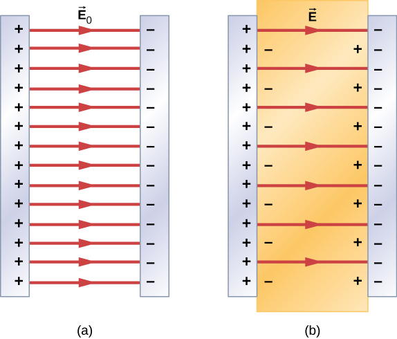
Portanto, quando a região entre as placas paralelas de um capacitor carregado, como a mostrada na Figura\(\PageIndex{3a}\), é preenchida com um dielétrico, dentro do dielétrico há um campo elétrico\(\vec{E}_0\) devido à carga livre \(Q_0\)nas placas do capacitor e um campo elétrico\(\vec{E}_i\) devido à carga induzida\(Q_i\) nas superfícies do dielétrico. Sua soma vetorial fornece o campo elétrico líquido\(\vec{E}\) dentro do dielétrico entre as placas do capacitor (mostrado na parte (b) da figura):
\[\vec{E} = \vec{E}_0 + \vec{E}_i. \label{eq1}\]
Esse campo de rede pode ser considerado o campo produzido por uma carga efetiva\(Q_0 - Q_i\) no capacitor.
In most dielectrics, the net electrical field \(\vec{E}\) is proportional to the field \(\vec{E}_0\) produced by the free charge. In terms of these two electrical fields, the dielectric constant \(\kappa\) of the material is defined as
\[\kappa = \dfrac{E_0}{E}. \label{eq2}\]
Since \(\vec{E}_0\) and \(\vec{E}_i\) point in opposite directions, the magnitude E is smaller than the magnitude \(\vec{E}_0\) and therefore \(\kappa > 1\). Combining Equations \ref{eq1} with \ref{eq2}, and rearranging the terms, yields the following expression for the induced electrical field in a dielectric:
\[\vec{E}_i = \left(\dfrac{1}{\kappa} - 1 \right) \vec{E}_0. \label{eq3}\]
When the magnitude of an external electrical field becomes too large, the molecules of dielectric material start to become ionized. A molecule or an atom is ionized when one or more electrons are removed from it and become free electrons, no longer bound to the molecular or atomic structure. When this happens, the material can conduct, thereby allowing charge to move through the dielectric from one capacitor plate to the other. This phenomenon is called dielectric breakdown. (Figure 8.1.1 shows typical random-path patterns of electrical discharge during dielectric breakdown.) The critical value, \(E_c\) of the electrical field at which the molecules of an insulator become ionized is called the dielectric strength of the material. The dielectric strength imposes a limit on the voltage that can be applied for a given plate separation in a capacitor. For example, the dielectric strength of air is \(E_c = 3.0 \, MV/m\), so for an air-filled capacitor with a plate separation of \(d = 1.00 \, mm\), the limit on the potential difference that can be safely applied across its plates without causing dielectric breakdown is \(V = E_c d = (3.0 \times 10^6 V/m)(1.00 \times 10^{-3} m) = 3.0 \, kV\).
However, this limit becomes 60.0 kV when the same capacitor is filled with Teflon™, whose dielectric strength is about \(60.0 \, MV/m\). Because of this limit imposed by the dielectric strength, the amount of charge that an air-filled capacitor can store is only \(Q_0 = \kappa_{air} C_0(3.0 \, kV)\) and the charge stored on the same Teflon™-filled capacitor can be as much as
\[\begin{align} Q &= \kappa_{teflon}C_0 (60.0 \, kV) \nonumber \\[4pt] &= \kappa_{teflon} \dfrac{Q_0}{\kappa_{air}(3.0 \, kV)} (60.0 \, kV) \nonumber \\[4pt] &= 20 \dfrac{\kappa_{teflon}}{\kappa_{air}}Q_0 = 20\dfrac{2.1}{1.00059}Q_0 \nonumber \\[4pt] &\cong 42 Q_0. \end{align} \]
which is about 42 times greater than a charge stored on an air-filled capacitor. Typical values of dielectric constants and dielectric strengths for various materials are given in Table \(\PageIndex{1}\). Notice that the dielectric constant \(\kappa\) is exactly 1.0 for a vacuum (the empty space serves as a reference condition) and very close to 1.0 for air under normal conditions (normal pressure at room temperature). These two values are so close that, in fact, the properties of an air-filled capacitor are essentially the same as those of an empty capacitor.
| Material | Dielectric constant \(\kappa\) | Dielectric strength \(E_c [\times 10^6 \, V/m]\) |
|---|---|---|
| Vacuum | \(\kappa\)">1 | \(E_c [\times 10^6 \, V/m]\)">\(\infty\) |
| Dry air (1 atm) | \(\kappa\)">1.00059 | \(E_c [\times 10^6 \, V/m]\)">3.0 |
| Teflon™ | \(\kappa\)">2.1 | \(E_c [\times 10^6 \, V/m]\)">60 to 173 |
| Paraffin | \(\kappa\)">2.3 | \(E_c [\times 10^6 \, V/m]\)">11 |
| Silicon oil | \(\kappa\)">2.5 | \(E_c [\times 10^6 \, V/m]\)">10 to 15 |
| Polystyrene | \(\kappa\)">2.56 | \(E_c [\times 10^6 \, V/m]\)">19.7 |
| Nylon | \(\kappa\)">3.4 | \(E_c [\times 10^6 \, V/m]\)">14 |
| Paper | \(\kappa\)">3.7 | \(E_c [\times 10^6 \, V/m]\)">16 |
| Fused quartz | \(\kappa\)">3.78 | \(E_c [\times 10^6 \, V/m]\)">8 |
| Glass | \(\kappa\)">4 to 6 | \(E_c [\times 10^6 \, V/m]\)">9.8 to 13.8 |
| Concrete | \(\kappa\)">4.5 | \(E_c [\times 10^6 \, V/m]\)">– |
| Bakelite | \(\kappa\)">4.9 | \(E_c [\times 10^6 \, V/m]\)">24 |
| Diamond | \(\kappa\)">5.5 | \(E_c [\times 10^6 \, V/m]\)">2,000 |
| Pyrex glass | \(\kappa\)">5.6 | \(E_c [\times 10^6 \, V/m]\)">14 |
| Mica | \(\kappa\)">6.0 | \(E_c [\times 10^6 \, V/m]\)">118 |
| Neoprene rubber | \(\kappa\)">6.7 | \(E_c [\times 10^6 \, V/m]\)">15.7 to 26.7 |
| Water | \(\kappa\)">80 | \(E_c [\times 10^6 \, V/m]\)">-− |
| Sulfuric acid | \(\kappa\)">84 to 100 | \(E_c [\times 10^6 \, V/m]\)">-− |
| Titanium dioxide | \(\kappa\)">86 to 173 | \(E_c [\times 10^6 \, V/m]\)">– |
| Strontium titanate | \(\kappa\)">310 | \(E_c [\times 10^6 \, V/m]\)">8 |
| Barium titanate | \(\kappa\)">1,200 to 10,000 | \(E_c [\times 10^6 \, V/m]\)">– |
| Calcium copper titanate | \(\kappa\)">> 250,000 | \(E_c [\times 10^6 \, V/m]\)">– |
Not all substances listed in the table are good insulators, despite their high dielectric constants. Water, for example, consists of polar molecules and has a large dielectric constant of about 80. In a water molecule, electrons are more likely found around the oxygen nucleus than around the hydrogen nuclei. This makes the oxygen end of the molecule slightly negative and leaves the hydrogens end slightly positive, which makes the molecule easy to align along an external electrical field, and thus water has a large dielectric constant. However, the polar nature of water molecules also makes water a good solvent for many substances, which produces undesirable effects, because any concentration of free ions in water conducts electricity.
Suppose that the distance between the plates of the capacitor in Example 8.5.1 is 2.0 mm and the area of each plate is \(4.5 \times 10^{-3} m^2\). Determine:
- the electrical field between the plates before and after the Teflon™ is inserted, and
- the surface charge induced on the Teflon™ surfaces.
Strategy
In part (a), we know that the voltage across the empty capacitor is \(V_0 = 40 \, V\), so to find the electrical fields we use the relation \(V = Ed\) and Equation \ref{eq3}. In part (b), knowing the magnitude of the electrical field, we use the expression for the magnitude of electrical field near a charged plate \(E = \sigma/\epsilon_0\), where \(\sigma\) is a uniform surface charge density caused by the surface charge. We use the value of free charge \(Q_0 = 8.0 \times 10^{-10} C\) obtained in Example 8.5.1.
Solution
- The electrical field \(E_0\) between the plates of an empty capacitor is \[E_0 = \dfrac{V_0}{d} = \dfrac{40 \, V}{2.0 \times 10^{-3} m} = 2.0 10^4 V/m. \nonumber\] The electrical field \(E\) with the Teflon™ in place is \[E = \dfrac{1}{\kappa}E_0 = \dfrac{1}{2.1}2.0 \times 10^4 V/m = 9.5 \times 10^3 \, V/m. \nonumber\]
- The effective charge on the capacitor is the difference between the free charge \(Q_0\) and the induced charge \(Q_i\). The electrical field in the Teflon™ is caused by this effective charge. Thus \[\begin{align*} E &= \dfrac{1}{\epsilon_0}\sigma \\[4pt] &= \dfrac{1}{\epsilon_0} \dfrac{Q_0 - Q_i}{A}.\end{align*}\] We invert this equation to obtain \(Q_i\), which yields \[\begin{align*} Q_i &= Q_0 - \epsilon_0AE \\[4pt] &= 8.0 \times 10^{-10}C - \left(8.85 \times 10^{-12} \dfrac{C^2}{N \cdot m^2}\right)(4.5 \times 10^{-3}m^2)\left(9.5 \times 10^3 \, \dfrac{V}{m}\right) \\[4pt] &= 4.2 \times 10^{-10}C = 0.42 \, nC. \end{align*} \nonumber\]
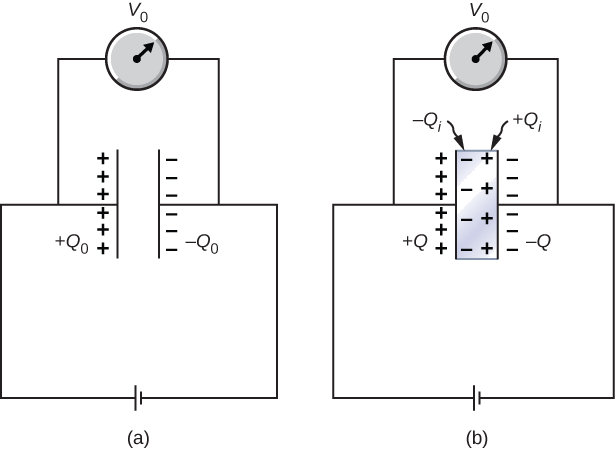
When a battery of voltage \(V_0\) is connected across an empty capacitor of capacitance \(C_0\), the charge on its plates is \(Q_0\), and the electrical field between its plates is \(E_0\). A dielectric of dielectric constant \(\kappa\) is inserted between the plates while the battery remains in place, as shown in Figure \(\PageIndex{4}\).
- Find the capacitance \(C\), the voltage \(V\) across the capacitor, and the electrical field \(E\) between the plates after the dielectric is inserted.
- Obtain an expression for the free charge \(Q\) on the plates of the filled capacitor and the induced charge \(Q_i\) on the dielectric surface in terms of the original plate charge \(Q_0\).
Strategy
We identify the known values:\(V_0, \, C_0, \, E_o, \, \kappa\), and \(Q_0\). Our task is to express the unknown values in terms of these known values.
Solution
(a) The capacitance of the filled capacitor is \(C = \kappa C_0\). Since the battery is always connected to the capacitor plates, the potential difference between them does not change; hence, \(V = V_0\). Because of that, the electrical field in the filled capacitor is the same as the field in the empty capacitor, so we can obtain directly that
\[E = \dfrac{V}{d} = \dfrac{V_0}{d} = E_0.\]
(b) For the filled capacitor, the free charge on the plates is
\[ \begin{align} Q &= CV \nonumber \\[4pt] &= (\kappa C_0)V_0 \nonumber \\[4pt] &= \kappa (C_0V_0) \nonumber \\[4pt] &= \kappa Q_0. \nonumber \end{align} \nonumber\]
The electrical field \(E\) in the filled capacitor is due to the effective charge \(Q - Q_i\) (Figure \(\PageIndex{4b}\)). Since \(E = E_0\), we have
\[\dfrac{Q - Q_i}{\epsilon_0 A} = \dfrac{Q_0}{\epsilon_0A}.\]
Solving this equation for \(Q_i\), we obtain for the induced charge
\[ \begin{align} Q_i &= Q - Q_0 \nonumber \\[4pt] &= \kappa Q_0 - Q_0 \nonumber \\[4pt] &= (\kappa -1)Q_0. \nonumber \end{align} \nonumber\]
Significance
Notice that for materials with dielectric constants larger than 2 (see Table \(\PageIndex{1}\)), the induced charge on the surface of dielectric is larger than the charge on the plates of a vacuum capacitor. The opposite is true for gasses like air whose dielectric constant is smaller than 2.
Continuing with Example \(\PageIndex{2}\), show that when the battery is connected across the plates the energy stored in dielectric-filled capacitor is \(U = \kappa U_0\) (larger than the energy \(U_0\) of an empty capacitor kept at the same voltage). Compare this result with the result \(U = U_0 /\kappa\) found previously for an isolated, charged capacitor.
Repeat the calculations of previous example for the case in which the battery remains connected while the dielectric is placed in the capacitor.
- Answer
-
a. \(C_0 = 20 \, pF\), \(C = 42 \, pF\);
b. \(Q_0 = 0.8 \, nC\), \(Q = 1.7 \, nC\):
c. \(V_0 = V = 40 \, V\);
d. \(U_0 = 16 \, nJ\), \(U = 34 \, nJ\)