
15.5 : Alimentation dans un circuit AC
- Page ID
- 191193

À la fin de la section, vous serez en mesure de :
- Décrire comment la puissance moyenne d'un circuit en courant alternatif peut être exprimée en termes de courant et de tension de pointe et de courant et de tension efficaces
- Déterminez la relation entre l'angle de phase du courant et de la tension et la puissance moyenne, connue sous le nom de facteur de puissance
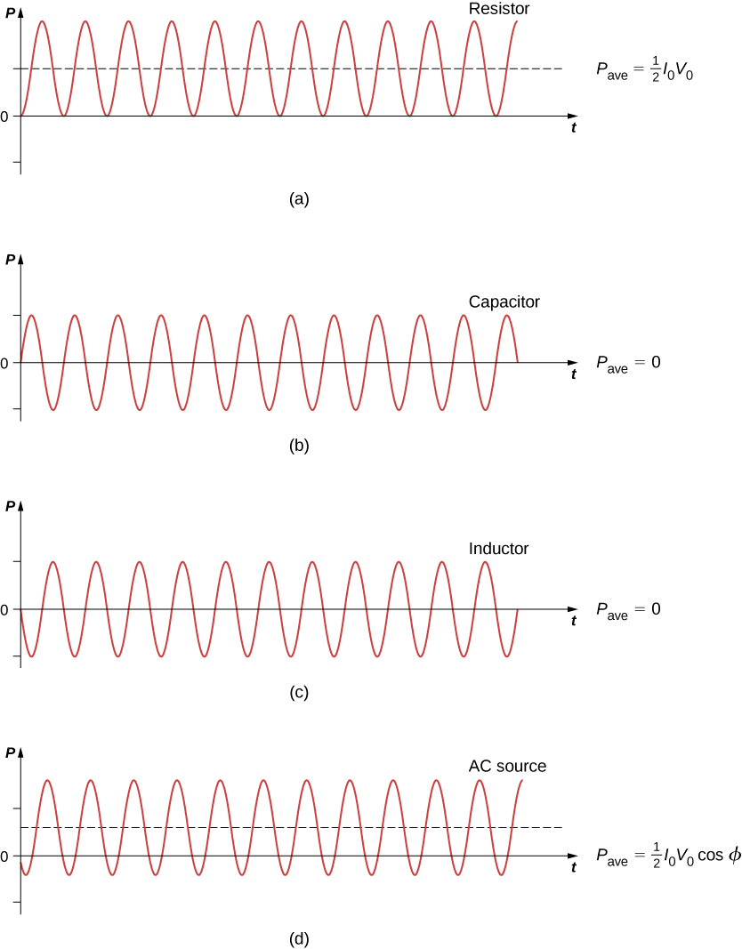
Un élément de circuit dissipe ou produit de l'énergie selon\(P = IV\), où I est le courant traversant l'élément et\(V\) la tension à ses bornes. Comme le courant et la tension dépendent tous deux du temps dans un circuit à courant alternatif, la puissance instantanée\(p(t) = i(t)v(t)\) dépend également du temps. Un diagramme\(p(t)\) de quatre éléments de circuit est illustré sur la figure\(\PageIndex{1}\). Pour une résistance,\(i(t)\) et\(v(t)\) sont en phase et ont donc toujours le même signe. Pour un condensateur ou une bobine d'induction, les signes relatifs\(i(t)\) et\(v(t)\) varient au cours d'un cycle en raison de leurs différences de phase. Par conséquent,\(p(t)\) est positif à certains moments et négatif à d'autres, ce qui indique que les éléments capacitifs et inductifs produisent de l'énergie à certains moments et l'absorbent à d'autres.
Because instantaneous power varies in both magnitude and sign over a cycle, it seldom has any practical importance. What we’re almost always concerned with is the power averaged over time, which we refer to as the average power. It is defined by the time average of the instantaneous power over one cycle:
\[P_{ave} = \dfrac{1}{T} \int_0^T p(t)dt, \label{eq41}\]
where \(T = 2\pi/\omega\) is the period of the oscillations. With the substitutions \(v(t) = V_0 \, \sin \, \omega t\) and \(i(t) = I_0 \, \sin \, (\omega t - \phi)\), Equation \ref{eq41} becomes
\[P_{ave} = \dfrac{I_0V_0}{T} \int_0^T \sin \, (\omega t - \phi) \, \sin \, \omega t \, dt. \nonumber\]
Using the trigonometric difference identity
\[\sin \, (A - B) = \sin \, A \, \cos \, B - \sin \, B \, \cos \, A \nonumber\]
we obtain
\[P_{ave} = \dfrac{I_0V_0 \, \cos \, \phi}{T} \int_0^T \sin^2 \omega t \, dt - \dfrac{I_0V_0 \, \sin \, \phi}{T} \int_0^T \sin \omega t \, \cos \, \omega t \, dt. \nonumber\]
Evaluation of these two integrals yields
\[\dfrac{1}{T} \int_0^T \sin^2 \omega t \, dt = \frac{1}{2} \nonumber\]
and
\[\dfrac{1}{T} \int_0^T \sin \omega t \, \cos \, \omega t \, dt = 0. \nonumber\]
Hence, the average power associated with a circuit element is given by
\[\boxed {P_{\mathrm{ave}}=\frac{1}{2} I_{0} V_{0} \cos \phi.} \label{eq5}\]
In engineering applications, \(\cos \phi\) is known as the power factor, which is the amount by which the power delivered in the circuit is less than the theoretical maximum of the circuit due to voltage and current being out of phase. For a resistor, \(\phi = 0\), so the average power dissipated is
\[P_{ave} = \dfrac{1}{2}I_0V_0. \label{eq6}\]
A comparison of \(p(t)\) and \(P_{ave}\) is shown in Figure \(\PageIndex{1d}\). To make Equation \ref{eq6} look like its dc counterpart, we use the rms values \(I_{rms}\) and \(V_{rms}\) of the current and the voltage. By definition, these are
\[I_{rms} = \sqrt{i_{ave}^2} \]
and
\[V_{rms} = \sqrt{v_{ave}^2},\]
where
\[t_{ave}^2 = \dfrac{1}{T} \int_0^T i^2(t)dt \]
and
\[v_{ave}^2 = \dfrac{1}{T} \int_0^T v^2(t)dt.\]
With \(i(t) = I_0 \, \sin \, (\omega t - \phi) \) and \(v(t) = V_0 \, \sin \, \omega t\), we obtain
\[I_{rms} = \dfrac{1}{\sqrt{2}}I_0 \]
and
\[V_{rms} = \dfrac{1}{\sqrt{2}}V_0.\]
We may then write for the average power dissipated by a resistor,
\[ P_{\text {ave }}=\frac{1}{2} I_{0} V_{0}=I_{\mathrm{rms}} V_{\mathrm{rms}}=I_{\mathrm{rms}}^{2} R. \label{eq10} \]
This equation further emphasizes why the rms value is chosen in discussion rather than peak values. Both Equations \ref{eq5} and \ref{eq10} are correct for average power, but the rms values in the formula give a cleaner representation, so the extra factor of 1/2 is not necessary.
Alternating voltages and currents are usually described in terms of their rms values. For example, the 110 V from a household outlet is an rms value. The amplitude of this source is \(110 \sqrt{2} \, V = 156 \, V\). Because most ac meters are calibrated in terms of rms values, a typical ac voltmeter placed across a household outlet will read 110 V.
For a capacitor and an inductor, \(\phi = \pi/2\) and \(-\pi/2 \, rad\), respectively. Since \(\cos \, \pi/2 = cos(-\pi/2) = 0\), we find from Equation \ref{eq5} that the average power dissipated by either of these elements is \(P_{ave} = 0\). Capacitors and inductors absorb energy from the circuit during one half-cycle and then discharge it back to the circuit during the other half-cycle. This behavior is illustrated in the plots of Figures \(\PageIndex{1b}\) and \(\PageIndex{1c}\) which show \(p(t)\) oscillating sinusoidally about zero.
The phase angle for an ac generator may have any value. If \(cos \, \phi > 0\), the generator produces power; if \(cos \, \phi < 0\), it absorbs power. In terms of rms values, the average power of an ac generator is written as
\[P_{ave} = I_{rms}V_{rms} \, \cos \, \phi.\]
For the generator in an RLC circuit,
\[tan \, \phi = \dfrac{X_L - X_C}{R}\] and
\[cos \, \phi = \dfrac{R}{\sqrt{R^2 + (X_L - X_C)^2}} = \dfrac{R}{Z}.\]
Hence the average power of the generator is
\[P_{ave} = I_{rms}V_{rms} \, \cos \, \phi = \dfrac{V_{rms}}{Z} V_{rms} \dfrac{R}{Z} = \dfrac{V_{rms}^2 R}{Z^2}. \label{eq30} \]
This can also be written as
\[P_{ave} = I_{rms}^2 R,\]
which designates that the power produced by the generator is dissipated in the resistor. As we can see, Ohm’s law for the rms ac is found by dividing the rms voltage by the impedance.
An ac generator whose emf is given by
\[v(t) = (4.00 \, V) \, \sin \, [(1.00 \times 10^4 \, rad/s)t] \nonumber\]
is connected to an RLC circuit for which \(L = 2.00 \times 10^{-3} H, \, C = 4.00 \times 10^{-6}F\), and \(R = 5.00 \, \Omega\).
- What is the rms voltage across the generator?
- What is the impedance of the circuit?
- What is the average power output of the generator?
Strategy
The rms voltage is the amplitude of the voltage times \(1/\sqrt{2}\). The impedance of the circuit involves the resistance and the reactances of the capacitor and the inductor. The average power is calculated by Equation \ref{eq30} because we have the impedance of the circuit \(Z\), the rms voltage \(V_{rms}\), and the resistance \(R\).
Solution
- Since \(V_0 = 4.00 \, V\), the rms voltage across the generator is \[V_{rms} = \dfrac{1}{\sqrt{2}} (4.00 \, V) = 2.83 \, V. \nonumber\]
- The impedance of the circuit is \[ \begin{align*} Z &= \sqrt{r^2 + (x_l - x_c)^2} \\[4pt] &= \sqrt{ (5.00 \,\Omega)^2 + \left[ (1.00 \times 10^4 \, rad/s)(2.00 \times 10^{-3} \, H) - \dfrac{1}{(1.00 \times 10^4 \, rad/s)(4.00 \times 10^{-6} \, F)} \right]^2 } \\[4pt] &= 7.07 \, \Omega. \end{align*} \]
- From Equation \ref{eq30}, the average power transferred to the circuit is \[P_{ave} = \dfrac{V_{rms}^2R}{Z^2} = \dfrac{(2.83 \, V)^2(5.00 \, \Omega)}{(7.07 \, \Omega)^2} = 0.801 \, W.\nonumber\]
Significance
If the resistance is much larger than the reactance of the capacitor or inductor, the average power is a dc circuit equation of \(P = V^2/R\), where V replaces the rms voltage.
An ac voltmeter attached across the terminals of a 45-Hz ac generator reads 7.07 V. Write an expression for the emf of the generator.
- Answer
-
\(v(t) = (10.0 \, V) \, \sin \, 90 \pi t\)
Show that the rms voltages across a resistor, a capacitor, and an inductor in an ac circuit where the rms current is \(I_{rms}\) are given by \(I_{rms}R, \, I_{rms}X_C\), and \(I_{rms}X_L\), respectively. Determine these values for the components of the RLC circuit of Equation \ref{eq5}.
- Answer
-
2.00 V; 10.01 V; 8.01 V