
4.3 : Moteurs thermiques
- Page ID
- 191129

À la fin de cette section, vous serez en mesure de :
- Décrire la fonction et les composants d'un moteur thermique
- Expliquer l'efficacité d'un moteur
- Calculez le rendement d'un moteur pour un cycle donné d'un gaz idéal
Un moteur thermique est un appareil utilisé pour extraire la chaleur d'une source, puis la convertir en un travail mécanique utilisé pour toutes sortes d'applications. Par exemple, une machine à vapeur sur un train à l'ancienne peut produire le travail nécessaire à la conduite du train. Plusieurs questions se posent concernant la construction et l'utilisation des moteurs thermiques. Par exemple, quel est le pourcentage maximum de chaleur extraite qui peut être utilisé pour effectuer des travaux ? Il s'avère que c'est une question à laquelle on ne peut répondre que par la deuxième loi de la thermodynamique.
La deuxième loi de la thermodynamique peut être formellement énoncée de plusieurs manières. L'une des déclarations présentées jusqu'à présent concerne la direction du flux de chaleur spontané, connue sous le nom de déclaration Clausius. Quelques autres affirmations sont basées sur les moteurs thermiques. Lorsque nous considérons les moteurs thermiques et les appareils associés tels que les réfrigérateurs et les pompes à chaleur, nous n'utilisons pas la convention de signalisation normale pour le chauffage et le travail. Pour des raisons pratiques, nous supposons que les symboles\(Q_h, \, Q_c\) A et W ne représentent que les quantités de chaleur transférées et de travail fourni, quels que soient les donneurs ou les récepteurs. Les panneaux appropriés placés devant les symboles et les directions des flèches dans les diagrammes indiquent si la chaleur entre ou sort d'un système et si le travail est effectué sur ou par un système.
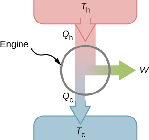
It turns out that we need more than one heat source/sink to construct a heat engine. We will come back to this point later in the chapter, when we compare different statements of the second law of thermodynamics. For the moment, we assume that a heat engine is constructed between a heat source (high-temperature reservoir or hot reservoir) and a heat sink (low-temperature reservoir or cold reservoir), represented schematically in Figure \(\PageIndex{1}\). The engine absorbs heat \(Q_h\) from a heat source (hot reservoir) of Kelvin temperature \(T_h\), uses some of that energy to produce useful work W, and then discards the remaining energy as heat \(Q_c\), into a heat sink (cold reservoir) of Kelvin temperature \(T_c\). Power plants and internal combustion engines are examples of heat engines. Power plants use steam produced at high temperature to drive electric generators, while exhausting heat to the atmosphere or a nearby body of water in the role of the heat sink. In an internal combustion engine, a hot gas-air mixture is used to push a piston, and heat is exhausted to the nearby atmosphere in a similar manner.
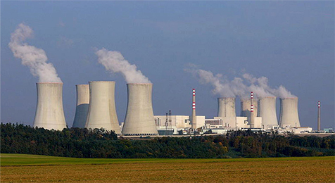
Actual heat engines have many different designs. Examples include internal combustion engines, such as those used in most cars today, and external combustion engines, such as the steam engines used in old steam-engine trains. Figure \(\PageIndex{2}\) shows a photo of a nuclear power plant in operation. The atmosphere around the reactors acts as the cold reservoir, and the heat generated from the nuclear reaction provides the heat from the hot reservoir.
Heat engines operate by carrying a working substance through a cycle. In a steam power plant, the working substance is water, which starts as a liquid, becomes vaporized, is then used to drive a turbine, and is finally condensed back into the liquid state. As is the case for all working substances in cyclic processes, once the water returns to its initial state, it repeats the same sequence.
For now, we assume that the cycles of heat engines are reversible, so there is no energy loss to friction or other irreversible effects. Suppose that the engine of Figure \(\PageIndex{1}\) goes through one complete cycle and that \(Q_h\), \(Q_c\), and W represent the heats exchanged and the work done for that cycle. Since the initial and final states of the system are the same, \(\Delta E_{int} = 0\) for the cycle. We therefore have from the first law of thermodynamics,
\[\begin{align} W &= Q - \Delta E_{int} \\[4pt] &= (Q_h - Q_c) - 0, \label{eq1} \end{align} \]
so that
\[W = Q_h - Q_c.\label{eq2} \]
The most important measure of a heat engine is its efficiency (e), which is simply “what we get out” divided by “what we put in” during each cycle, as defined by
\[e = \dfrac{W_{out}}{Q_{in}}. \label{eq3}\]
With a heat engine working between two heat reservoirs, we get out \(W\) and put in \(Q_h\), so the efficiency of the engine is
\[\begin{align} e &= \dfrac{W}{Q_h} \\[4pt] &= 1 - \dfrac{Q_c}{Q_h}. \label{eq4} \end{align} \]
Here, we used Equation \ref{eq2}, in the final step of this expression for the efficiency.
A lawn mower is rated to have an efficiency of \(25\%\) and an average power of 3.00 kW. What are
- the average work and
- the minimum heat discharge into the air by the lawn mower in one minute of use?
Strategy
From the average power—that is, the rate of work production—we can figure out the work done in the given elapsed time. Then, from the efficiency given, we can figure out the minimum heat discharge \(Q_c = Q_h(1 - e)\) with \(Q_h = Q_c + W\).
Solution
- The average work delivered by the lawn mower is \[\begin{align} W &= P\Delta t \\[4pt] &= 3.00 \times 10^3 \times 60 \times 1.00 \, J \\[4pt] &= 180 \, kJ.\end{align} \]
- The minimum heat discharged into the air is given by \[\begin{align} Q_c &= Q_h(1 - e) \\[4pt] &= (Q_c + W)(1 - e), \end{align} \] which leads to \[\begin{align} Q_c &= W(1/e - 1) \\[4pt] &= 180 \times (1/0.25 - 1)kJ = 540 \, kJ. \end{align} \]
Significance
As the efficiency rises, the minimum heat discharged falls. This helps our environment and atmosphere by not having as much waste heat expelled.