
3.3 : Travail, chaleur et énergie interne
- Page ID
- 190956

À la fin de cette section, vous serez en mesure de :
- Décrire le travail effectué par un système, le transfert de chaleur entre les objets et le changement d'énergie interne d'un système
- Calculez le travail, le transfert de chaleur et la variation d'énergie interne en un processus simple
Nous avons discuté des concepts de travail et d'énergie plus tôt en mécanique. Des exemples et des problèmes connexes de transfert de chaleur entre différents objets ont également été abordés dans les chapitres précédents. Nous souhaitons ici étendre ces concepts à un système thermodynamique et à son environnement. Plus précisément, nous avons développé les concepts de chaleur et de transfert de chaleur dans les deux chapitres précédents. Ici, nous voulons comprendre comment le travail est effectué par ou vers un système thermodynamique ; comment la chaleur est transférée entre un système et son environnement ; et comment l'énergie totale du système change sous l'influence du travail effectué et du transfert de chaleur.
Travail effectué par un système
Une force créée à partir de n'importe quelle source peut fonctionner en déplaçant un objet. Alors, comment fonctionne un système thermodynamique ? La figure\(\PageIndex{1}\) montre un gaz confiné dans un cylindre doté d'un piston mobile à une extrémité. Si le gaz se dilate contre le piston, il exerce une force à distance et agit sur le piston. Si le piston comprime le gaz lorsqu'il est déplacé vers l'intérieur, un travail est également effectué, dans ce cas, sur le gaz.
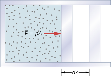
The work associated with such volume changes can be determined as follows: Let the gas pressure on the piston face be p. Then the force on the piston due to the gas is pA, where A is the area of the face. When the piston is pushed outward an infinitesimal distance \(dx\), the magnitude of the work done by the gas is
\[dW = F \, dx = p A \, dx.\nonumber \]
Since the change in volume of the gas is \(dV = A \, dx\), this becomes
\[dW = pdV.\nonumber \]
For a finite change in volume from \(V_1\) to \(V_2\), we can integrate this equation from \(V_1\) to \(V_2\) to find the net work:
\[W = \int_{V_1}^{V_2} p\,dV. \label{eq5}\]
This integral is only meaningful for a quasi-static process, which means a process that takes place in infinitesimally small steps, keeping the system at thermal equilibrium. (We examine this idea in more detail later in this chapter.) Only then does a well-defined mathematical relationship (the equation of state) exist between the pressure and volume. This relationship can be plotted on a pV diagram of pressure versus volume, where the curve is the change of state. We can approximate such a process as one that occurs slowly, through a series of equilibrium states. The integral is interpreted graphically as the area under the pV curve (the shaded area of Figure \(\PageIndex{2}\)). Work done by the gas is positive for expansion and negative for compression.
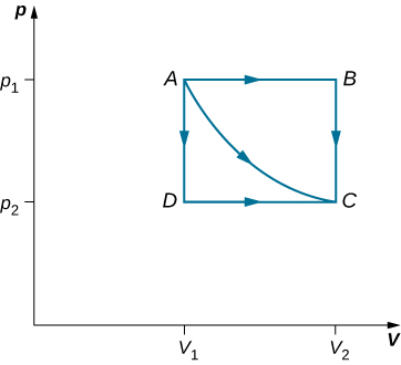
Consider the two processes involving an ideal gas that are represented by paths AC and ABC in Figure \(\PageIndex{3}\). The first process is an isothermal expansion, with the volume of the gas changing its volume from \(V_1\) to \(V_2\). This isothermal process is represented by the curve between points A and C. The gas is kept at a constant temperature T by keeping it in thermal equilibrium with a heat reservoir at that temperature. From Equation \ref{eq5} and the ideal gas law,
\[W = \int_{V_1}^{V_2} pdV = \int_{V_1}^{V_2} \left(\dfrac{nRT}{V}\right) dV.\nonumber \]
The expansion is isothermal, so \(T\) remains constant over the entire process. Since n and R are also constant, the only variable in the integrand is V, so the work done by an ideal gas in an isothermal process is
\[W = nRT \int_{V_1}^{V_2} \dfrac{dV}{V} = nRT ln \dfrac{V_2}{V_1}.\nonumber \]
Notice that if \(V_2 > V_1\) (expansion), W is positive, as expected.
The straight lines from A to B and then from B to C represent a different process. Here, a gas at a pressure \(p_1\) first expands isobarically (constant pressure) and quasi-statically from \(V_1\) to \(V_2\), after which it cools quasi-statically at the constant volume \(V_2\) until its pressure drops to \(p_2\). From A to B, the pressure is constant at p, so the work over this part of the path is
\[W = \int_{V_1}^{V_2} pdV = p_1 \int_{V_1}^{V_2} dV = p_1(V_2 - V_1).\nonumber \]
From B to C, there is no change in volume and therefore no work is done. The net work over the path ABC is then
\[W = p_1(V_2 - V_1) + 0 = p_1 (V_2 - V_1).\nonumber \]
A comparison of the expressions for the work done by the gas in the two processes of Figure \(\PageIndex{3}\) shows that they are quite different. This illustrates a very important property of thermodynamic work: It is path dependent. We cannot determine the work done by a system as it goes from one equilibrium state to another unless we know its thermodynamic path. Different values of the work are associated with different paths.
Studies of a van der Waals gas require an adjustment to the ideal gas law that takes into consideration that gas molecules have a definite volume (see The Kinetic Theory of Gases). One mole of a van der Waals gas has an equation of state
\[\left(p + \dfrac{a}{V_2}\right) (V - b) = RT,\nonumber \]
where a and b are two parameters for a specific gas. Suppose the gas expands isothermally and quasi-statically from volume \(V_1\) to volume \(V_2\). How much work is done by the gas during the expansion?
Strategy Because the equation of state is given, we can use Equation \ref{eq5} to express the pressure in terms of V and T. Furthermore, temperature T is a constant under the isothermal condition, so V becomes the only changing variable under the integral.
Solution To evaluate this integral, we must express p as a function of V. From the given equation of state, the gas pressure is
\[p = \dfrac{RT}{V - b } - \dfrac{a}{V^2}.\nonumber \]
Because T is constant under the isothermal condition, the work done by 1 mol of a van der Waals gas in expanding from a volume \(V_1\) to a volume \(V_2\) is thus
\[ \begin{align*} W &= \int_{V_1}^{V_2} \left(\dfrac{RT}{V - b} - \dfrac{a}{V^2} \right) dV \\[4pt] &= \left[RT \ln(V - b) + \frac{a}{V}\right]_{V_1}^{V_2} \\[4pt] &= RT \ln \left(\dfrac{V_2 - b}{V_1 - b}\right) + a \left(\dfrac{1}{V_2} - \dfrac{1}{V_1} \right).\end{align*}\]
Significance
By taking into account the volume of molecules, the expression for work is much more complex. If, however, we set \(a = 0\) and \(b = 0\) we see that the expression for work matches exactly the work done by an isothermal process for one mole of an ideal gas.
How much work is done by the gas, as given in Figure \(\PageIndex{3}\), when it expands quasi-statically along the path ADC?
- Answer
-
\(p_2(V_2 - V_1)\)
Internal Energy
The internal energy \(E_{int}\) of a thermodynamic system is, by definition, the sum of the mechanical energies of all the molecules or entities in the system. If the kinetic and potential energies of molecule i are \(K_i\) and \(U_i\) respectively, then the internal energy of the system is the average of the total mechanical energy of all the entities:
\[E_{int} = \sum_i (\overline{K}_i + \overline{U}_i),\nonumber \]
where the summation is over all the molecules of the system, and the bars over K and U indicate average values. The kinetic energy \(K_i\) of an individual molecule includes contributions due to its rotation and vibration, as well as its translational energy \(m_iv_i^2/2\) where \(v_i\) is the molecule’s speed measured relative to the center of mass of the system. The potential energy \(U_i\) is associated only with the interactions between molecule i and the other molecules of the system. In fact, neither the system’s location nor its motion is of any consequence as far as the internal energy is concerned. The internal energy of the system is not affected by moving it from the basement to the roof of a 100-story building or by placing it on a moving train.
In an ideal monatomic gas, each molecule is a single atom. Consequently, there is no rotational or vibrational kinetic energy and \(K_i = m_iv_i^2/2\). Furthermore, there are no interatomic interactions (collisions notwithstanding), so \(U_i = constant\), which we set to zero. The internal energy is therefore due to translational kinetic energy only and
\[E_{int} = \sum_i \overline{K}_i = \sum_i \dfrac{1}{2}m_i\overline{v}_i^2.\nonumber \]
From the discussion in the preceding chapter, we know that the average kinetic energy of a molecule in an ideal monatomic gas is
\[\dfrac{1}{2}m_iv_i^2 = \dfrac{3}{2}k_BT,\nonumber \]
where T is the Kelvin temperature of the gas. Consequently, the average mechanical energy per molecule of an ideal monatomic gas is also \(3k_BT/2\), that is
\[\overline{K_i + U_i} = \overline{K}_i = \dfrac{3}{2}k_BT.\nonumber \]
The internal energy is just the number of molecules multiplied by the average mechanical energy per molecule. Thus for n moles of an ideal monatomic gas,
\[E_{int} = nN_A\left(\dfrac{3}{2}k_BT\right) = \dfrac{3}{2} nRT.\nonumber \]
Notice that the internal energy of a given quantity of an ideal monatomic gas depends on just the temperature and is completely independent of the pressure and volume of the gas. For other systems, the internal energy cannot be expressed so simply. However, an increase in internal energy can often be associated with an increase in temperature.
We know from the zeroth law of thermodynamics that when two systems are placed in thermal contact, they eventually reach thermal equilibrium, at which point they are at the same temperature. As an example, suppose we mix two monatomic ideal gases. Now, the energy per molecule of an ideal monatomic gas is proportional to its temperature. Thus, when the two gases are mixed, the molecules of the hotter gas must lose energy and the molecules of the colder gas must gain energy. This continues until thermal equilibrium is reached, at which point, the temperature, and therefore the average translational kinetic energy per molecule, is the same for both gases. The approach to equilibrium for real systems is somewhat more complicated than for an ideal monatomic gas. Nevertheless, we can still say that energy is exchanged between the systems until their temperatures are the same.